I covered this topic before. But if it doesnt work, there's another workaround. I got the idea from here. So thank you. I'm reposting what I did to fix it here.
Okay first some background. Your problem is that Office 2010/2013 apps dont print but other programs like notepad, browsers, etc can print. You already tried re installing office, changing to or from 64/32 bit office, and re installing the printer driver. You even tried the tip in my other post. If those dont work do this.
I'm doing it in win 8 64 bit but it should work the same for win 7.
* Go to control panel.
* Go to Devices and Printers.
* Click on "Add a printer". I chose at random the LPT1 and the HP deskjet 4320.
* Do not make it the default printer.
Thats it. MS office should print OK from now on.
Showing posts with label fix. Show all posts
Showing posts with label fix. Show all posts
Tuesday, January 22, 2013


Wednesday, January 9, 2013
Ms Office 2010 does not print
Have you ever installed MS Office and it doesnt print however other programs like browsers, notepad, etc do print?
The first thing you should do is check your printer drivers.
If that doesnt work a workaround is to install a PDF converter, preferably freeware like Cute PDF. Set cute PDF as the printer, print and save as a PDF file. Then open the PDF and print.
But a workaround is not satisfying. Here's the real fix.
For MS publisher, go to the FILE tab then click options. Click Advanced then scroll down to Print. There's only one option : Use XPS enhanced print path when available. Un check this.
For MS word, go to the FILE tab then click options. Click Advanced then scroll down to Print. There are several options. Try unchecking Print in background.
A reboot might be necessary.
the end
The first thing you should do is check your printer drivers.
If that doesnt work a workaround is to install a PDF converter, preferably freeware like Cute PDF. Set cute PDF as the printer, print and save as a PDF file. Then open the PDF and print.
But a workaround is not satisfying. Here's the real fix.
For MS publisher, go to the FILE tab then click options. Click Advanced then scroll down to Print. There's only one option : Use XPS enhanced print path when available. Un check this.
For MS word, go to the FILE tab then click options. Click Advanced then scroll down to Print. There are several options. Try unchecking Print in background.
A reboot might be necessary.
the end
Thursday, February 16, 2012
altec lansing ahs 515 cord repair
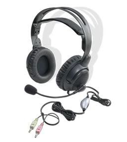
My headphone has been repaired before in this previous blog post. Now the wire insulation is fraying right after the volume control.
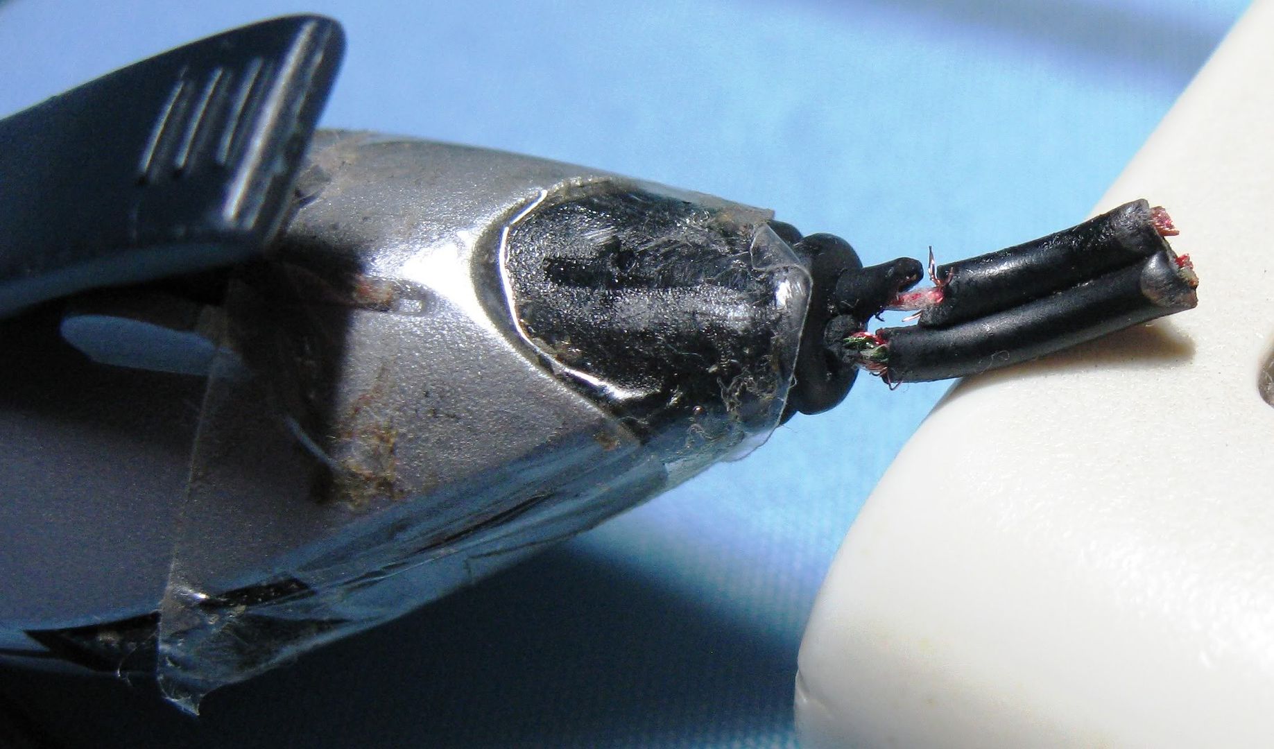
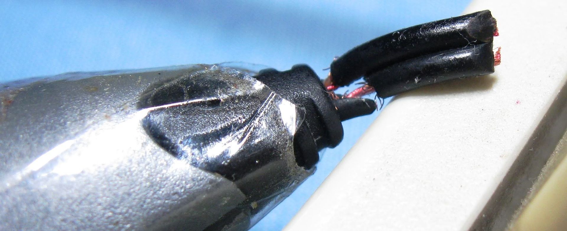
Since the volume control is useless anyway, I opted to cut it out and re attach the wire. Step 1 is to knot the wires together, remove the insulation, and splay out the wires.
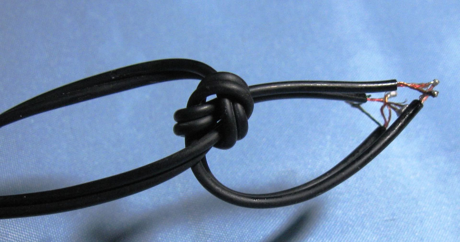
Next step is to Identify which wire goes to which. Fortunately, the mic cable only has 2 wires and the while speaker cable has 3 so there's no mixing them up. And the wires are color coded with what looks like varnish. It also serves as insulation.
It was a simple matter to tin the ends of the wires and solder them together. After this, I checked the headset on my PC. I used the audio driver's settings to check if both left and right channels were working.
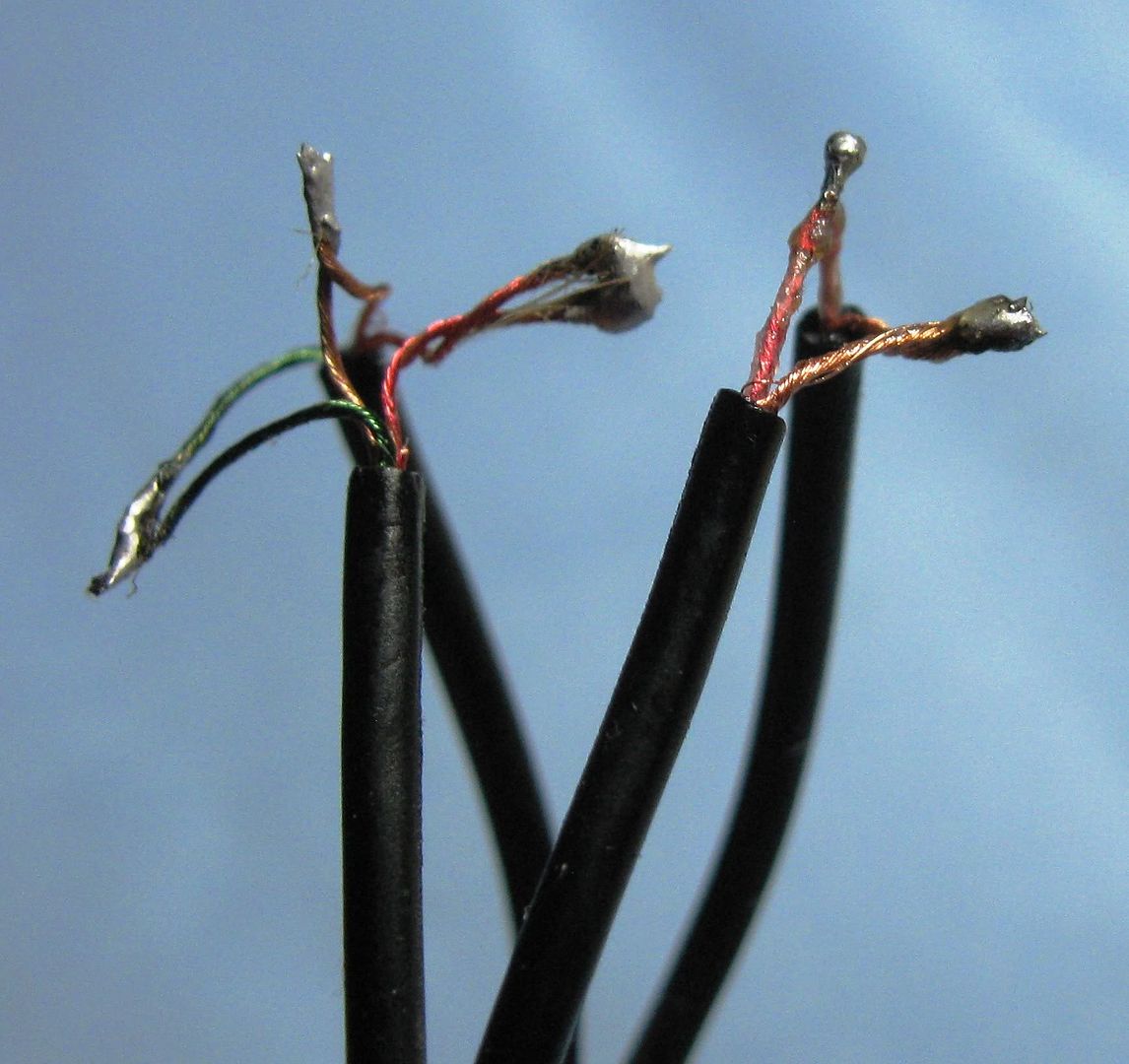
Next, carefully cover the blobs of solder with electrical tape. I ended up using 3 layers in total.

OK that's it. Instead of buying a new pair of headphones, I just repaired mine. Saved me some money.
the end
Tuesday, August 23, 2011
second generation LED maglite repair
If you read my older posts here, you know that my family has a few second generation led maglite 2AA flashlights. My mom uses hers practically every day. Lots of scratches and its fallen from the table a few times. But this time, the light died.
I was dismayed. I though maglites were indestructible! I initially despaired of being able to fix it and bought a cheap cdrking LED flashlight as a temporary replacement. A few days later, my mom asked about the flashlight and she suggested that I disassemble it and try to repair it.
So now, I'm at my desk, poking and prodding at the flashlight. It was empty, i.e. no batteries. I removed the end cap and was poking the emitter head back and forth when this fell out. By the way, its normal for the emitter head to move like that.

Its a plastic holder with the positive electrode for the batteries on the posterior end and a circuit board inside. There are 2 electrical slots on the inside posterior end of the plastic holder which should match with the 2 contacts on one end of the board.
UPDATE: the circuit board can be inserted onto the black plastic holder in 2 directions. Since the holder is pretty symmetrical, its difficult to know which direction is correct. So you can try using trial and error.


This gave me hope. I thought that if I could get at the emitter head, I might have a chance of ficing this. I thought about asking in a flashlight message board that I'm a member of. But before asking, I decide to search for "maglite dissasemble" in the forums. I found this.
OK so this gave me hope. I opted to use a small hammer and a chopstick to remove the emitter head.

I placed the tip of the chopstick on the metal beside the actual LED and VERY GENTLY began tapping with a hammer. Eventually, the metal emitter head fell down through the back end of the flashlight body. A black plastic ring remained which fell out the forward end of the flashlight body. The ring serves to lock the head in place
UPDATE: you can use your fingers to press the metal emitter head down instead of using a hammer.

I just re-assembled the emitter head, the board and the black holder. The emitter head has 3 electrical slots on its back so the end of the circuit board with 3 electrical contacts goes there. But I noticed that there are no positive and negative signs and the board can go in 2 ways. I thought, OK go for broke, 50/50 chance. I'm just hoping that what maglite says about the electronics being vulnerable to reverse current flow isnt true.
UPDATE: The metal emitter head has writing on one side and the other side as seen in the picture above has no writing. For standardization purposes, the side of the circuit board with the cylindrical black plastic cylinder with wire coiled around it and a "100" printed on top faces the side of the metal emitter head which has writing on it. And getting it backwards doesn't seem to fry the electronics if you don't try it for too long.
I placed the emitter in the back end of the flashlight body and placed 2 AA batteries after the emitter. I then pushed the batteries upwards with my finger. The emitter head is now in the proper place. I got the black ring and pushed it through the front end of the body and with a gentle push, locked the head in place. I then tried the flashlight, IT WORKS!!!!
the end
I was dismayed. I though maglites were indestructible! I initially despaired of being able to fix it and bought a cheap cdrking LED flashlight as a temporary replacement. A few days later, my mom asked about the flashlight and she suggested that I disassemble it and try to repair it.
So now, I'm at my desk, poking and prodding at the flashlight. It was empty, i.e. no batteries. I removed the end cap and was poking the emitter head back and forth when this fell out. By the way, its normal for the emitter head to move like that.

Its a plastic holder with the positive electrode for the batteries on the posterior end and a circuit board inside. There are 2 electrical slots on the inside posterior end of the plastic holder which should match with the 2 contacts on one end of the board.
UPDATE: the circuit board can be inserted onto the black plastic holder in 2 directions. Since the holder is pretty symmetrical, its difficult to know which direction is correct. So you can try using trial and error.


This gave me hope. I thought that if I could get at the emitter head, I might have a chance of ficing this. I thought about asking in a flashlight message board that I'm a member of. But before asking, I decide to search for "maglite dissasemble" in the forums. I found this.
I used two screwdrivers and just pushed the LED module out the other end. Now for reassembling...
OK so this gave me hope. I opted to use a small hammer and a chopstick to remove the emitter head.

I placed the tip of the chopstick on the metal beside the actual LED and VERY GENTLY began tapping with a hammer. Eventually, the metal emitter head fell down through the back end of the flashlight body. A black plastic ring remained which fell out the forward end of the flashlight body. The ring serves to lock the head in place
UPDATE: you can use your fingers to press the metal emitter head down instead of using a hammer.

I just re-assembled the emitter head, the board and the black holder. The emitter head has 3 electrical slots on its back so the end of the circuit board with 3 electrical contacts goes there. But I noticed that there are no positive and negative signs and the board can go in 2 ways. I thought, OK go for broke, 50/50 chance. I'm just hoping that what maglite says about the electronics being vulnerable to reverse current flow isnt true.
UPDATE: The metal emitter head has writing on one side and the other side as seen in the picture above has no writing. For standardization purposes, the side of the circuit board with the cylindrical black plastic cylinder with wire coiled around it and a "100" printed on top faces the side of the metal emitter head which has writing on it. And getting it backwards doesn't seem to fry the electronics if you don't try it for too long.
I placed the emitter in the back end of the flashlight body and placed 2 AA batteries after the emitter. I then pushed the batteries upwards with my finger. The emitter head is now in the proper place. I got the black ring and pushed it through the front end of the body and with a gentle push, locked the head in place. I then tried the flashlight, IT WORKS!!!!
the end
Friday, November 12, 2010
dual car cigarette lighter fix
This is the Car Plug Splitter from CDRKing. The usb charger on the right was bought separately.

 .
.
Right away there are problems. The stock lighter that comes with my car only fits in one of the holes, is loose, and it doesnt work. Its brand new, still in warranty, but I could not resist the urge to hack it.
Here's what it looks like inside.

Right away I see a safety problem. There is a hole in the front and I see a piece of stiff wire covered by shrink tubing. However the tip is exposed and is very near a metal part where it could short.

Upon opening the tube I see a resistor.

So it looks like there used to be a LED light in the hole. Well, I cant leave this fixed so I bent the end of the resistor and covered it with shrink tubing.

Here you see why the cigarette lighter doesnt work. There is a several mm gap (red arrow) so it doesnt make contact.

The solution is simple. I need to make electrical contact with the central post of the lighter

I solder on a spiral of stiff copper wire. To make the solder stick, I had to abrade the metal (probably iron) with sandpaper.


To make the lighter less loose, I merely smeared some solder on the inside

UPDATE: unfortunately the lighter still isnt working. I think the wire moved a little to the side and doesnt make contact with the central post. more testing needed. To be continued
The end
.Right away there are problems. The stock lighter that comes with my car only fits in one of the holes, is loose, and it doesnt work. Its brand new, still in warranty, but I could not resist the urge to hack it.
Here's what it looks like inside.
Right away I see a safety problem. There is a hole in the front and I see a piece of stiff wire covered by shrink tubing. However the tip is exposed and is very near a metal part where it could short.
Upon opening the tube I see a resistor.
So it looks like there used to be a LED light in the hole. Well, I cant leave this fixed so I bent the end of the resistor and covered it with shrink tubing.
Here you see why the cigarette lighter doesnt work. There is a several mm gap (red arrow) so it doesnt make contact.
The solution is simple. I need to make electrical contact with the central post of the lighter
I solder on a spiral of stiff copper wire. To make the solder stick, I had to abrade the metal (probably iron) with sandpaper.
To make the lighter less loose, I merely smeared some solder on the inside
UPDATE: unfortunately the lighter still isnt working. I think the wire moved a little to the side and doesnt make contact with the central post. more testing needed. To be continued
The end
Tuesday, October 12, 2010
Logitech v220 repair
Disclaimer: I am in no way connected with any hardware or software company. I have not been paid any compensation to write this blog post.
 1. INTRODUCITON
I've used logitech mice for a long time. They work and the most important attribute for me is their toughness. I can expect them to last at least 2 years under me and this makes up for their higher price. This particular logitech v220 cordless mouse is of around 2008 vintage. I use it for my laptop. Its not a gaming laptop so I have never used it for games much but I do not feel any lag. I chose it because it was the cheapest logitech wireless mouse at the time with AA. It uses a single AA battery and I prefer AA batteries because I try to standardize all my stuff to have AA batteries. That way, I have lots of spares and I can swap batteries among my gadgets.
This mouse has served me well and as is common with most mice, the left mouse button is the most used part and it tends to die first. In this case the problem is the left button sometimes double clicks when I give it a single click. It started a few months ago and it is getting worse so I decided to try to repair it. To be on the safe side I already checked out my local mall and I know the prices of the major models and brands of wireless mice. Since I always want to save money and I have a little free time and talent, lets expend time and talent instead of expending or spending money.
Essentially what is wrong with my mouse is a malfunctioning left microswitch or clicker. Here's a picture.

You have to replace the defective left clicker since I doubt actually fixing it is within my skillset. You can buy one, you can cannibalize one from another mouse which happens to use a similar sized clicker. Or you can merely swap the left and right clickers, which is what I decided to do.
2. DISSASEMBLING THE LOGITECH V220
The first thing you need to do is to open up the battery cover. To do that you press the big button on the bottom marked with the battery symbol. I've encircled it in red in the picture below. Press that with your fingertip and the cover pops open.

Take out the battery. You can see a screw (screwhole encircled with red) but you do not need to remove it.

Now you need to unscrew the casing. But where are the screws? Well, as is common with most manufacturers, they are hidden. In this case under the mouse feet. All 4 of the feet have to be pried open at least partially. I just used a fingernail.

Next, detach the power cable. There are 2 catches that lock the connector. Depress them with a paperclip or other tool then yank it off.


Next step is to unscrew the circuit board from the bottom half of the case. There are 2 screws, one also attaches the scroll wheel.

Now you have the bare circuit board in your hands.


Turn it over and look for the 3 soldered contacts below each clicker.

You need to unsolder all 3 contact points simultaneously. Prepare for it by first removing the antenna. Its the big shiny steel wire that wraps around the circuit board.You need to remove the antenna as it is in the way.

Next de solder the contacts. If you dont have the proper equipment you can just use a length of braided copper wire. Prepare the wire by soaking it in solder flux or rosin so it will "wet" with molten lead better. Heat the wire and let it melt the solder at the contacts. Capillary action will draw the solder onto the wire. As the wire fills up with solder just cut off the tip.
Once you have cleaned up the extra solder, apply heat to all 3 contacts simultaneously by using the side of your soldering iron or gun while at the same time apply tension or pull on the clicker. I just grab the clicker with my fingertips and push the circuit board with my knuckles. The clicker should fall off. Before you remove the clickers, I suggest you mark the left and right clickers so you don't mix them up.


The hard part is over. Merely switch the clickers and solder them into place. Make sure that the bottoms of the clickers are almost flush against the circuit board. Resolder the antenna. Screw the circuit board back to the bottom half of the case and make sure the on/off switch at the bottom of the mouse is working. Re-attach the power cable and insert a battery to confirm that the mouse is working. You should see the green power LED light up on the circuit board.
Next, replace the upper half of the case but before re-screwing the 4 screws under the feet, press the case together and test all the mouse buttons on your PC. Once you know it is working, replace the 4 screws and press back the mouse feet. There should be some contact cement left so the feet should stick but you can apply glue if you want. There you have it, a resurrected logitech v220 mouse.
The end.
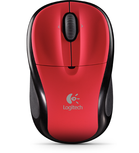
I've used logitech mice for a long time. They work and the most important attribute for me is their toughness. I can expect them to last at least 2 years under me and this makes up for their higher price. This particular logitech v220 cordless mouse is of around 2008 vintage. I use it for my laptop. Its not a gaming laptop so I have never used it for games much but I do not feel any lag. I chose it because it was the cheapest logitech wireless mouse at the time with AA. It uses a single AA battery and I prefer AA batteries because I try to standardize all my stuff to have AA batteries. That way, I have lots of spares and I can swap batteries among my gadgets.
This mouse has served me well and as is common with most mice, the left mouse button is the most used part and it tends to die first. In this case the problem is the left button sometimes double clicks when I give it a single click. It started a few months ago and it is getting worse so I decided to try to repair it. To be on the safe side I already checked out my local mall and I know the prices of the major models and brands of wireless mice. Since I always want to save money and I have a little free time and talent, lets expend time and talent instead of expending or spending money.
Essentially what is wrong with my mouse is a malfunctioning left microswitch or clicker. Here's a picture.

You have to replace the defective left clicker since I doubt actually fixing it is within my skillset. You can buy one, you can cannibalize one from another mouse which happens to use a similar sized clicker. Or you can merely swap the left and right clickers, which is what I decided to do.
2. DISSASEMBLING THE LOGITECH V220
The first thing you need to do is to open up the battery cover. To do that you press the big button on the bottom marked with the battery symbol. I've encircled it in red in the picture below. Press that with your fingertip and the cover pops open.
Take out the battery. You can see a screw (screwhole encircled with red) but you do not need to remove it.
Now you need to unscrew the casing. But where are the screws? Well, as is common with most manufacturers, they are hidden. In this case under the mouse feet. All 4 of the feet have to be pried open at least partially. I just used a fingernail.
Next, detach the power cable. There are 2 catches that lock the connector. Depress them with a paperclip or other tool then yank it off.
Next step is to unscrew the circuit board from the bottom half of the case. There are 2 screws, one also attaches the scroll wheel.
Now you have the bare circuit board in your hands.
Turn it over and look for the 3 soldered contacts below each clicker.
You need to unsolder all 3 contact points simultaneously. Prepare for it by first removing the antenna. Its the big shiny steel wire that wraps around the circuit board.You need to remove the antenna as it is in the way.
Next de solder the contacts. If you dont have the proper equipment you can just use a length of braided copper wire. Prepare the wire by soaking it in solder flux or rosin so it will "wet" with molten lead better. Heat the wire and let it melt the solder at the contacts. Capillary action will draw the solder onto the wire. As the wire fills up with solder just cut off the tip.
Once you have cleaned up the extra solder, apply heat to all 3 contacts simultaneously by using the side of your soldering iron or gun while at the same time apply tension or pull on the clicker. I just grab the clicker with my fingertips and push the circuit board with my knuckles. The clicker should fall off. Before you remove the clickers, I suggest you mark the left and right clickers so you don't mix them up.
The hard part is over. Merely switch the clickers and solder them into place. Make sure that the bottoms of the clickers are almost flush against the circuit board. Resolder the antenna. Screw the circuit board back to the bottom half of the case and make sure the on/off switch at the bottom of the mouse is working. Re-attach the power cable and insert a battery to confirm that the mouse is working. You should see the green power LED light up on the circuit board.
Next, replace the upper half of the case but before re-screwing the 4 screws under the feet, press the case together and test all the mouse buttons on your PC. Once you know it is working, replace the 4 screws and press back the mouse feet. There should be some contact cement left so the feet should stick but you can apply glue if you want. There you have it, a resurrected logitech v220 mouse.
The end.
Subscribe to:
Posts (Atom)
projectwonderful adszz
